Sunday, December 6, 2015

Save 65%: Hack Your Own Coravin Argon Gas Capsules

The Coravin Wine Preservation System is fantastic. It’s an easy way to dispense wine without pulling the cork since the device cleverly replacing the excess volume with argon instead of oxygen (the enemy of wine). You can pour just a glass or two at a time and easily save the rest of the bottle for later.

However, the Coravin Argon Capsules are almost $10 each. And while they claim to pour 15 glasses of wine, they never seem to actually make it that far. As a result, we end up going through a capsule for every 2-3 bottles meaning there’s a “Coravin Tax” of up to $5.00 per bottle. Ouch!

Turns out there’s a cheaper way. While the Coravin Capsules claim to be proprietary, the metal cylinder is just a standard 3.5” food grade argon capsule. The only unique part of the capsule is the plastic cap.


This cap houses a very important rubber o-ring that ensures a good seal between the capsule and the Coravin. So, all we need to do is remove this cap from a used capsule and we can use it with much cheaper non-Coravin capsules!

To do this, grab a pair of channellock pliers for the metal body and a smaller pair of pliers for the cap. Grab the capsule with one set and the tip of the plastic cap with the other. Make sure you have a secure grip on both and turn counter clockwise if you’re facing the top of the capsule. With a little effort, you’ll unstick the glue and at which point you can easily unscrew the cap.


There are plenty of options for 3.5” food grade argon capsule. The cheapest I’ve been able to find are for another, much less effective, wine preservation system called Preservino. These capsules come in either a 4-pack or an 8-pack and in the larger case are only about $3.50 each for a savings of $6.50 per capsule!


Simply slip the cap you removed from the Coravin capsule onto one of the standard capsules. Pop this new capsule in your Coravin and you’re in business!


Tuesday, January 10, 2012

Making a Belgian Pale Ale

Home beer making has become pretty popular lately, so much so that there are physical stores that stock supplies for it. My friends and I were interested and made some beer beer using a starter kit we bought a while back.

For this batch we decided to make a Belgian Pale Ale. While more advanced home brewers will construct their own recipes, we're still fairly new at this so we just went to the home brew store and picked up their starter kit. An important point to note about this is that we're doing "extract brewing" here as opposed to "all grain brewing", the difference being that we're using malt extract to get the sugar that the yeast needs.

Step 1: Getting Ready
If you ask any home brewer what the most important part of brewing in, they'll answer "sanitation." While the final product of this process is resistant to spoilage, they key to getting there consistently and safely is ensuring no biological baddies get to your beer before the yeast does.

As a result it is very important to thoroughly wash everything that will come in contact with the beer. We use two products called PBW (Powdered Brewery Wash) for removing organic deposits and Star San which is an odorless no-rinse sanitizer.


Step 2: Making the Wort
After everything has been cleaned, it's time to get down to the real work and make some beer. The first step, of course, is to make the concoction that the yeast eats and turns into delicious beer, the wort. This is a pretty simple process when you're doing extract brewing like we're doing here. You basically brew a tea by bringing a large batch of water to a rolling boil and adding the malt extract, hops, and other ingredients as specified by the recipe.


Step 3: Fermentation
Once you've completed your wort, it's time to make the magic happen. Here sanitation becomes a big issue again. You now have what is effectively a giant petri dish that'll grown any microorganism that is introduced. You want this to be your yeast.

The first part of this is cooling down the wort as quickly as possible. We did this in an ice bath while the wort was still in the aluminum pot to aid in heat transfer. This can be done much more quickly using a copper cooling coil with circulating water, but we didn't have one of those. Once the wort was at the temperature appropriate for the yeast we we syphoned it into the glass (not plastic) carboy where the yeast would be introduced and the fermentations would take place.


After the cooled wort had been transferred to the glass carboy we introduced the yeast. An important part of "pitching" the yeast is giving it enough air for it to start doing it's job. Knowing that we had messed this up in the past, we shook the capped carboy for a full 15 minutes, trading off when someone was getting tired. As usual, there are better tools for this (aerators like you use in a fish tank) but we didn't have one of those.

At this point, you've done all you can do, it's time to let the yeast do their magic. We let this particular batch sit about two weeks while the sugars in our wort got transformed into alcohol. Note that for better results, you'll measure the density of the wort and temperature before and after so you know how much of the sugar has been turned into alcohol. We didn't do this because we were lazy. However, we did decide to track the temperature of our wort to make sure our yeast wasn't being shocked since it had been a problem before.

In the graph you can see how much steadier and cooler the closet stayed than the hallway on the other side of the door. A closet is a good place to ferment beer.

Step 4: Bottling and Drinking
After two weeks of fermentation it was finally time to bottle the beer. Many people put their beer in a keg and then force carbonate it. This reduces the TTD (time to drunk) and gives you more consistent carbonation. However, as is the trend, we didn't have that equipment so we did it the old fashioned way. We filled and capped 48 bottles and let the yeast ferment a little more in the bottle. This provided the CO2 needed for the carbonation after another week or so. The final result was delicious and definitely worth the wait!


Here's a link to the web album with all the pictures from the process.

Technologies: Yeast, Arduino, Fire

Make Beautiful Scuba Diving Videos on the Cheap

About a year and a half ago, I learned how to scuba dive. Living within driving distance of Monterey, CA this has turned into an amazing weekend activity. The volume and diversity of wildlife means no two dives are the same. However, when many of my friends and family that don't dive, it's nice to be able to share part of that experience with them.

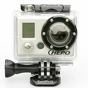
The GoPro HD Hero helmet camera is a great way to do that. It's cheap (relative to other underwater cameras), waterproof to 60m (200 ft) and indestructible. It also has a variety of accessories from extended batteries, to LCD preview screens that allow for flexible configurations.

When diving, how you mount your equipment can make or break a dive. If you're constantly fiddling with your gear you risk not paying attention to important things like air and depth.  If it's not attached properly, you might lose it. Both will ruin your day.

My first attempt with this camera was using GoPro's chest harness. This kept the camera securely attached and for the most part out of the way. However, my BCD inflater hose would regularly flop in front of it, blocking my shot, and it was very difficult to point it at what I wanted filmed.

After having too many fish drift just outside of the frame, I decided that I needed a better solution. I picked up a tripod mount from GoPro started putting together a monopod. While there are commercially available monopod camera extenders, none of them are very well suited for diving either because they're not very durable or they're constructed of material that corrodes easily in saltwater.


PVC pipe was an excellent choice of material for this project. It doesn't corrode in saltwater and it's easy to work with. For the connection to the camera, I found a bolt with the same threading as a standard tripod at the hardware store. I secured this to a PVC cap using epoxy and a nut. From there on, it was just PVC pipe glue with segments spaced appropriately to attach retractors. I also wrapped the largest (bottommost) segment with duct tape to provide better grip.


When put together it can be used either in third person mode (left) or camcorder mode (right). The former lets me tape some cool shots of myself and my dive buddy and the latter makes it much easier to keep the fish of interest in frame when combined with the LCD panel. Combined with the amazing video quality of the GoPro then end result is amazing. You can see clips that take advantage of both of the configurations from a dive to Point Lobos in Carmel, CA below.


Technologies: GoPro HD HERO, Adobe Premier Pro, PVC pipe


Thursday, November 3, 2011

Building a 8 Channel Solid State Relay Board

Have you ever seen videos of those insane Christmas light displays? Those displays are usually controlled by large banks of solid state relays turning on and off each strand to time with the music. I bough a bunch of these relays on eBay and wanted to make my own general purpose controller that I could use in other projects.

Warning: Mains electricity is dangerous if not handled properly. Do not try and do this project unless you have sufficient training in handling it.

The Relays
The solid state relays I used were super simple. Mine were a little different but in general this class of relay all look the same. There are 4 screw terminals on either side of the relay. (1) and (2) are the load that's switched on an off, the polarity of which doesn't matter and on my relays could be up to 240V and 10A AC (on this one it's 25A). (3) and (4) are the input that controls the relay. The polarity does matter here and the control voltage can be anywhere between 3 to 32VDC.  This wide range of input voltages makes it really easy to control with something like an Arduino.

Step 1: Safely wiring all the mains electronics

A very important part of any project like this is to correctly and safely wire the mains electricity part of the board. When you are dealing with low voltages while tinkering with electronics, if you mess up the worst thing that can happen is you destroy your circuit. With mains electricity you can kill yourself or start a fire.

As a result, it was important to safely contain any of the AC components so they could not be accidentally touched as well as ensure complete connections so there was no unintended buildup of heat. I used a set of 4 junction boxes each with 4 plugs (two on each channel) as the way to connect whatever was being controlled. Out of those I ran wire of a proper gauge to plugs and plugged them into power strips. I considered going less bulky but decided since this was my first big AC project, that I'd keep the safety as simple as possible.

The harder part was safely putting the relays in line with this circuit. I snipped one wire out of each of the cables and attached the (1) and (2) terminals on the relay in series with it. I then screwed the relays down on the wood and covered them with plexiglass.


With that all set up I was successfully able to turn off each of these circuits using a 9V battery.

Step 2: Control

The control for this project was very simple. Each of those relays is essentially just an LED. All that I needed to do was hook up the positive side of each terminal to a different digital out on my Arduino and then all the negative sides to ground. I ran all of this cabeling through a set of DB9 connectors to keep it sane. Also, since I wanted to be able to remove the Arduino from wherever this board was installed, I mounted it in it's own enclosure with a female DB9 connector.


Step 3: Program

The code for this project on the Arduino and the computer was dead simple. The Arduino just read a byte off of the serial port and turned on the relays corresponding to the bits in that byte. The computer just writes bytes to the serial port.

Here's the final result. Definitely a bit bulkier than it needs to be, but it works and it's safe.


Technologies: Solid State Relays, A/C Electronics, Arduino

Wednesday, October 26, 2011

Measuring How Far Your Hamster Runs

In a previous post I talked a lot about how far my hamster ran. You can measure this yourself too. I've written up an Instructable with step by step instructions but I also wanted to give an overview here.

Theory: Since my hamster did most of her running in her wheel, it made sense to count revolutions of the wheel and multiply that by the circumference. Being an avid cyclist, I knew of a device that already did this, my bike speedometer.


There are two important elements here, the magnet and the sensor. This sensor is rather simple, it's just a reed switch that is triggered every time a magnet comes near it. I just needed to construct something like this on the hamster wheel and hook it up to the computer.

Second, I needed to figure out was how to read the state of this switch from the computer. There are all sorts of ways to do this but I was looking for something quick, easy, and cheap. It turns out that the serial port on your computer has two pins DTR (Data Terminal Ready) and DSR (Data Set Ready) that'll be sufficient. In code, you can control the DTR pin and read the DSR pin. By shorting the two through the reed switch you can check whether or not it's on.

Construction: I found most of what I needed for this around the house.


In addition to a wheel and our hamster, I used:

  1. reed switch (from a home security system)
  2. DB9 female DSUB solder connector (i.e. a female serial port connector)
  3. magnet (from a hard drive)
  4. mounting supplies (pen, zip ties, glue)
  5. wire (thick so the hamster can't chew through it)

Putting this together was rather simple. I just attached the pen to the wheel with some zip ties and glue and then attached the reed switch to the pen.  I broke the magnet in half and used it to keep itself in place. After that I just needed to wire it up and connect each side of the switch to the DTR and DSR pins on the serial port connector.


Now I just needed to write some code. I did this in python but this can be written in any language with a serial port library.


import serial
ser = serial.Serial("/dev/ttyS1")
circumference = 0.000396 # miles
 
def waitForPinOff():
  while ser.getDSR() == 1:
    1 # Don't do anything while we wait.
 
def waitForPinOn():
  while ser.getDSR() == 0:
    1 # Don't do anything while we wait.
 
ser.setDTR(1) 
while 1:
  waitForPinOn()
  waitForPinOff()
  distance = distance + circumference

All this is doing is connecting to the serial port and turning on DTR (i.e. setting the pin to 5V). It then waits to see DSR turn on (i.e. the switch is closed) and increments the distance by the circumference every time that happens. There's a couple things you I did to clean up the data from there (and here's some better code for that) but that's basically it! Here's the final set up with Lizzie the hamster.


Technologies: Magnet, Reed Switch, Basic Electronics, Python, Hamster

Monday, October 24, 2011

Improved Traffic Light Bike Light

This projects was done a while ago (1/6/2010) but it's never too late to post!

The first iteration of this project worked quite well. However, it wasn't very compact because the blinking was done by an external Arduino board which was overkill, messy, and needed a separate power supply. So for the second iteration of this project, I decided to make the control circuitry contained entirely within the UPS.

Step 1: Make a blinker circuit. It turns out this is really easy to do with a simple 555 timer IC and some help online. I picked my resistors and capacitors to give this a duty cycle similar to other bike lights I owned. This is a picture of the circuit on a breadboard before I soldered it up to protoboard that shows how simple it is.


Step 2: Find power in the UPS. It didn't make any sense to power this thing externally when I was dealing with uninterruptible power supply with plenty of control circuity. The 555 timer I bought works with anywhere between 4.5V and 16V. So I turned the thing on and carefully probed measured various places on the board until I found one that was giving me 12 volts. After that, getting the electronics working was as simple as soldering it all together.


Step 3: Put it back together. Finally I was ready to make it look pretty. I taped up wires, put the 555 circuit in some extra space, and added a couple a couple doses of hot glue. Afterwards you wouldn't suspect that I had been in there are all. Success!


I did actually use this on a few rides to and from work and it worked splendidly if a bit heavy because of the lead acid battery. Especially at night, the traffic light is amazingly bright. A great next step would be ripping out all of the AC circuity and getting this working with some lighter batteries DC only.

Technologies: A/C Electronics, Basic Electronics, soldering iron

Thursday, January 14, 2010

Linguo: a Telepresence Robot Using an iRobot Create

Two Christmases ago my roommates gave me an iRobot Create. I decided to make a telepresence robot similar to the one my friend, Damon, constructed.


Hardware
The key electronic components were:
  • iRobot Create® Programmable Robot
  • Samsung NC10 Netbook
  • Quickcam 4000 (an old one I had lying around)
The hard parts in constructing this robot was mounting everything cleanly and securely. I turned to acrylic and a laser cutter for this task. While this was my first foray into this type of construction, it went very well. A critical step in this process was constructing a prototype using cardboard and hot glue. This caught several physical mistakes that came as a result of my poor spatial reasoning.


Software
With the hardware in place, I wrote two quick python scripts to control Linguo. One to get the commands from the user and the other to actually control the robot. These talked via Skype using its API. Skype was an excellent choice for this project because both video and audio came for free. In addition communication is done between screen names so there was no worrying about changing IP addresses.

The control script was pretty simple. It initiates a call via Skype, maps key presses to commands, and sends those commands as a Skype text message.


The other script (the one controlling the robot) automatically answered the call (super convenient), turned on the video, and waited for commands. When it received commands and requests, it controlled the Create and read from its sensors using PyRobot.

Lessons
  • Everyone's first reaction to Linguo is to stand in front of it and "see what it does." Damn you human curiosity!
  • People are very hard to identify by their shoes.
  • Houses are surprisingly dark, it would have been nice to have a flashlight.
  • Operating live controls (i.e. where the length of the button press denotes how far the robot should go) over a high latency connection is very frustrating.
  • Don't think driving the robot in your room next to your computer is truly the same as controlling it from New York to San Francisco (which I did). You miss very important things like having a detailed charge and battery status and important perspective on how hard it is to drive using just the camera and microphone.
  • Telepresense is frikin' awesome!
Technologies: iRobot Roomba, Python, Skype, TkInter, PyRobot